Cracking Open the ASUS Eee 901 20G ultra-portable

The ""="" href="http://www.techrepublic.com/contents/2346-10877_11-211254.html?tag=gald">ASUS Eee 901 20G is one of the new ultra-portable PC-like devices hitting the market. It is trying to fill a niche where consumers want power and long-battery life in an ultra-small and extremely portable package. We just had to ""="" href="http://www.techrepublic.com/search/search/cracking" open.html="">crack open our ASUS 901 take a look inside and check out its design and engineering.
Often the best plan for Cracking Open a piece of electronic equipment is through its soft underbelly.
So it is going to be like that is it. The yellow circle marks the first hidden screw. I guess it is going to be obvious we opened our ASUS 901 up. There goes the warranty.
If the warranty was still in effect, this information would be important. Alas.
The ASUS case is held together by six Phillips Head screws -- at least that is how it appears.
The ASUS 901 has a double cell Lithium-Ion battery pack. That helps to explain the device's longer battery life.
Two screws later (one partially hidden under a piece of tape) and the back door pops off to reveal the RAM board and the 20GB solid state hard drive.
The back door is covered in aluminum foil -- I am not sure why. Do you have a guess?
The RAM and solid state drive are connection to the ASUS 901 via seemingly standard connections. That should mean that the device is fairly easy to upgrade - assuming the internal components can handle increased capacities.
The RAM board appears to be fairly standard notebook RAM. I simply opened the clips that held the board in place and removed it.
""="" href="http://www.elpida.com/en/index.html">Elpida Memory, Inc. is a large Japanese company specializing in the manufacture of DRAM memory chips.
The solid state drive is next -- it looks to be a simple removal.
To remove the solid-state drive we need to remove the two highlight screws.
Samsung made the 20GB solid state drive.
The flip side of the solid state drive contains more Samsung made chips. This is probably one of the more expensive parts in our ASUS 901.
At this point I have removed all of the visible screws, but the case will not separate. There must be some hidden screws somewhere - but where?
That's right - there are eight screws under the keyboard. And one has a warning piece of tape over it - I guess the warranty is really out the window now.
The ASUS 901 keyboard is not the best keyboard I have ever seen. It is very thin and flimsy. I'd better not bang on it like I do most keyboards.
The keyboard and the touch pad connect to the motherboard via ribbon cable -- I hate ribbon cables like this because they are difficult to get back in their respective slots.
Our first clear look at the ASUS 901 motherboard. There are lots of chips on this motherboard, but the layout is surprisingly roomy.
The star of the motherboard of course is the Intel 945 Express chipset for mobile computing. The three main components, the Atom CPU, the Graphics chip, and the controller are highlighted.
The three main chips dominate the motherboard. The yellow highlights where the thermal paper stuck to the controller chip.
The Atom CPU is small and designed to be used in small mobile devices.
The ""="" href="http://www.intel.com/products/processor/atom/techdocs.htm">Atom CPU from Intel is one of many CPUs produced by that large conglomerate operation. The data sheet can fill you in on where the Atom falls into the Intel product line.
Intel also has a long line of inexpensive, low-energy consuming, graphics chips in their product line. This one was spit-cleaned by Bill Detwiler as he passed by the Cracking Open lab table. I quickly moved on to the next chip.
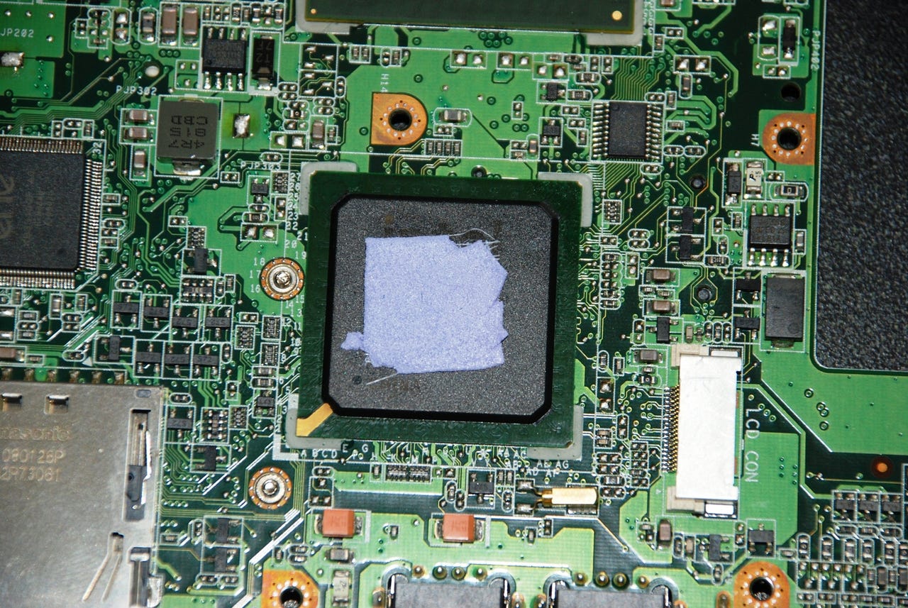
The thermal tape used to help transfer heat to the metal supporting the top portion of the case stuck to the controller chip. Bill was not satisfied with that and insisted we remove it.
This chips handles the I/O for the ASUS 901.
This is where the thermal tape should be.
The thermal paste is back in its spot.
The tape is not perfect, but it should be good enough.
The controlling chip for the SD card reader is from ""="" href="http://www.ene.com.tw/en/index.asp">ENE Technology, Inc.
Just above the Intel controller chip is the LCD connection. The ASUS 901 has a very bright and vibrant LCD screen.
The connection under the tape that I didn't see until I started to remove the motherboard goes to the fan, which we will see later.
The other side of the motherboard contains several important parts for our ASUS 901 Eee.
In this image you can see where that battery connection went and you can see more memory chips. These chips must store persistent information like operating system preferences.
The silver rectangle in the image houses our wireless chips. Besides the controlling chip provided by ENE Technologies, Inc. we also have a chip made by ""="" href="http://www.phison.com/English/productView.asp?ID=136&SortID=8">Phison. The yellow highlights mark the poles for the antennae.
In this corner we find several chips involved in the production of sound for the ASUS Eee. The one with the highlight should be familiar to us -- it is a ""="" href="http://www.realtek.com.tw/">High-Definition sound chip from RealTek.
The yellow highlight marks the speaker connection and the red highlight marks a multimedia controller chip. I would like to know the manufacturer, but I don't see any logos or names. Can anyone help us with that?
Here is another shot of the SD card reader.
This is an overview of the underside of the case. Note the various connecting wires and the speakers.
There is indeed a fan to help dissipate heat from the ASUS Eee. However, as the arrows show, the fan pulls air across and away from the solid state hard drive and the RAM board. The chips apparently get most of their heat dissipated by the casing which constitutes a large heat sink.
And because everyone always asks: I put it back together and it still works just fine. In fact, I'm going to put some different operating systems on it just to see what that looks like.